Engineering Analysis/Design
Modified Drumsticks
The stick setup for VPS is a closed system that combines the accelerometer data with a microcontroller (Arduino) that sets off the pager motors once the acceleration hits a particular threshold. The motivation for this design was to allow for haptic feedback. Accelerometers are mounted to the stick tips which trigger pager motors imbedded in the other end of the stick. The accelerometers used are the ADXL345 since they use the I2C protocol, which allowed for fewer wires. We were also able to use the alternate address setup, which allowed us to use only one Arduino to read information from both sticks.
Although the accelerometer is not fully necessary for the implementation of an air drum set, it will allow us to (1) create a methodology for feedback and triggering, (2) allow us to decrease the latency between the physical motion and the sound output and (3) increase resolution of acceleration data for better amplitude differentiation.
In selecting the type of accelerometer, we must take a variety of characteristics into account. First of all, the device must be small because we are attaching it to a pair of drumsticks. The size is important because we want to maintain a sleek form factor that is not going to distract from the general use of the device. One of the fundamental classifications for accelerometers is how many directions of measurements the chip takes (axes). For our case, the minimum we should have is a 2-axis accelerometer. This is because we are only really interested in the planar acceleration perpendicular to the drumstick. Despite this, there is a lot more availability of 3-axis accelerometers. Furthermore, in order to decrease latency, we looked for accelerometers with an Serial Peripheral Interface protocol setup, which provides the fastest sampling frequency among other common protocols such as I2C and UART. The last quality necessary in the accelerometer is the acceleration range. Reference [9] found that the range of accelerations we should expect is from 0-7 g's (relative to Earth's standard gravity). Although this article contains data from trials, we found that we were successfully able to differentiate accelerations with a $\pm$ 16g range.
We ultimately decided upon using the ADXL345 for several reasons. First of all, it satisfies all the conditions delineated in the previous paragraph. It seems to be a general purpose 3-axis SPI accelerometer with the added advantage that there are pre-written Arduino codes to process the information. Additionally, it has an adjustable range so if we were able to play with parameters and increase it to $\pm$ 16g range.
The pager motor, was chosen to fit inside the butt of the drumstick. The heaviest standard drumstick (size 5A) weighs 3.2 ounces, so we did want to minimize the weight of the pager motor and other components in order to keep the stick below 3.2 ounces. We decided upon a 6.35 mm diameter pager motor because it could snugly fit onto either the stick or the glove for haptic feedback. All the characteristics, included in Figure 20, are within reason to implement.
The accelerometers are mounted to custom designed, 3D printed mounts. To accommodate these mounts, the ends of the sticks were removed and a shallow hole drilled in the top end of the stick, which held a peg on the mount. The mount was designed to fit into the accelerometer breakout board such that little to no other form of fixation was necessary (Figure 5). The engineering drawing for this device is shown in the Appendix under Figure 18. Another larger hole was drilled in the butt-end of the stick, which was just large enough to fit the pager motors. The pager motors were fit snuggly into this hole, then secured with hot glue.

Haptic feedback was determined using only the accelerometers. We chose not to incorporate the Leap motion because of the complexities of transferring information from the Arduino to Unity. The ADXL345 interfaces nicely with Arduino, and many libraries exist for communication. We decided that only the magnitudes in the x and y directions were necessary, neglecting the z direction that runs axially down the stick. If this magnitude surpasses a threshold value, the pager motors are triggered.
The pager motors (1597-1246-ND) are controlled by the Arduino via pulse-width modulation (PWM). The intensity and duration of each burst were determined through experimentation - we wanted the user to feel a buzz that mimicked hitting a drum, but also ensure that it did not trail into the next drum strike. The motors were controlled using the same Arduino as the accelerometers.

The circuit diagram for the accelerometer/pager motor system can be seen in the Appendix under Figure 17.
Kick Pedal
The kick drum and hi-hat are critical components to any drum set, and both are controlled at least in part through the use of a foot pedal. In order to replicate the feel of a traditional drum set, it is necessary to create a lightweight, but still realistic, version of the traditional kick drum pedal.
We decided to use an existing pedal rather than fabricate our own - a Guitar Hero video game controller. The device includes the pedal, spring, as well as the button used by the game system to trigger the kick drum. The figure below shows the pedal and attached 3.5mm cable used by the game system.

Though weight and portability are of great importance, a pre-made pedal has been selected to shorten the design and build process. Future developmental goals consist of shortening the overall pedal to decrease the size and weight of the device, and choosing materials that will give the user control as well as durability, or possibly eliminating the traditional pedal design all together and creating a more compact pad.
For the purposes of the VPS, both position and velocity of the kick drum pedal are important: position of the pedal will denote when the kick drum is hit, while the angular velocity of the pedal will control volume. This was accomplished using a linear potentiometer as a voltage divider. The potentiometer was mounted such that the action of the pedal will cause a corresponding change in resistance. As the resistance changes, we are able to measure a change in voltage and determine the angle of the kick pedal. Differentiating this data gives a rough estimate of velocity to be used to determine the volume of the corresponding sound.


The schematic below shows how the potentiometer can be used to measure the position of the kick drum pedal.

The resistance of the potentiometer will change in a way that is proportional to the movement of the slider (Resistance is $R = \frac{\rho l}{A}$, $l$ is length, $\rho$ resistivity, and $A$ cross sectional area). Figure X(a) can be equated to Figure X(b) for any position of the slider, where $ R_1 + R_2 = 10 k\Omega$. The voltage output to the ADC can be computed as:
$$V_{ADC} = (5V) \frac{R_2}{R_1+R_2} = (5V) \frac{R_2}{10 k\Omega}$$
As can be seen in the equation above, the output voltage is also proportional to the movement of the slider. The position of the kick pedal can be determined once at least two known points are determined.
An Arduino functions as an Analog to Digital Converter (ADC). The arduino can function as a 10 bit ADC, which over a range of 0 to 5 V gives a resolution of about 4.8 mV. The To get an estimate of the velocity of the kick, we selected to take an average of the velocity after the kick pedal passes a certain height threshold. The Guitar Hero pedal has a movement range of 3.5 cm, so we chose to use the range of velocities found while the pedal was depressed greater than 3 cm. This average velocity was then mapped to a value from 1 to 10, then passed to Unity via serial monitor.
Software
The software interface is essentially shown in the Concept Description section. We are using the Unity game engine to develop our software interface because it allows for the extension to various platforms and interfaces well with the Leap Motion.
The game environment for the VPS has two types of game objects: the drums and the sticks. Each game object has a region called a collider that is used to detect collisions with other game objects. Unity allows for actions to be taken on collision start, which we use to produce the correct sound when each drum is struck. Sound is produced through a sound module. Additionally, Unity can measure the magnitude of each collision, allowing for volume control. The schematic is shown below in Figure 11. Our game software basically works in the following steps:
- Arduino passes kick drum velocity data to Unity, and Unity program is actively listening for data every timestep.
- In the Unity environment, drums and two spheres representing the tip of the tracked sticks are defined as game objects and they are set to “rigid bodies”, and we can tune the associated “collider” position and size. When two colliders meet, the system would detect a “collision” between two rigid bodies.
- The drum game objects have audiosource attached, and they would generate a sound upon a collision.
- The sphere has a position update script attached. It utilizes the tool tracking feature of Leap motion sensor, and we have to scale and tune the positions to match normal human motion.
- The bass drum has additional script attached, which listens to the data from serial port. Once it receives the kick drum velocity data, it would activate the audio source attached and play a audio with volume adjusted by the kick drum velocity.

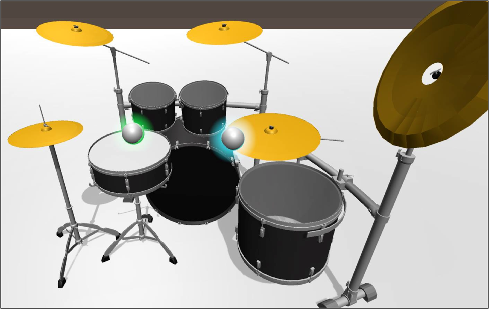
The figure below shows the final software interface of the VPS. The limited size of the drum set was selected to reduce the chance of a user missing the intended drum. The sticks are represented by the green and blue spheres which track the end of each drumstick. These have been initialized such that the green stick is the leftmost stick, and the blue stick is the rightmost stick.